Sasha Fratini

MSc Electronic Engineering Student

Semiconductor processes, digital IC and MEMS design, embedded firmware and FMCW radar for automotive.

Skills

Skills developed through MSc coursework, laboratory work, cleanroom activities and the thesis internship.

  • Semiconductor processes

    Fabrication process flow and cleanroom activities: thin-film deposition (CVD, PVD) and photoresist deposition. Thin-film optical coating design and TCAD simulation.

    Process flow · CVD · PVD · Photoresist · Synopsys Sentaurus TCAD

  • Digital design

    Hardware description in VHDL, FPGA synthesis with Quartus Prime and functional verification in ModelSim. Background in VLSI design and CPU architecture.

    VHDL · FPGA · Quartus Prime · ModelSim · VLSI · CPU architecture

  • MEMS

    MEMS device design and finite-element multiphysics simulation in COMSOL Multiphysics.

    MEMS design · COMSOL Multiphysics

  • Embedded systems

    C firmware for STM32 (HAL, LL, CubeMX), TI CC26xx BLE SoCs and TI mmWave radar SoCs, with a focus on low power consumption.

    STM32 · TI CC26xx BLE · TI mmWave · Low-power firmware

  • Signal processing

    FMCW radar for automotive applications: chirp design, DBSCAN clustering of detections and object tracking.

    FMCW radar · DBSCAN · Object tracking

  • Programming

    C for embedded firmware, Python for algorithms and prototyping, MATLAB/Simulink for simulation and numerical optimization, VHDL for hardware description.

    C · Python · MATLAB/Simulink · VHDL

  • Electronic CAD

    PCB design in Cadence OrCAD, together with Cadence Presto and AutoCAD.

    Cadence OrCAD · Cadence Presto · AutoCAD

  • Languages

    Italian (native); English at B2 level (CEFR), with language courses in New York (2019) and Bournemouth (2018).

    Italian · English B2 CEFR

Projects

Code, plots and diagrams from my GitHub repositories.

ecobin · BLE sensor · 2026

Fill-level monitoring over BLE

Smart waste-bin sensor: an ultrasonic sensor measures the fill level and a TI CC26xx SoC transmits it over Bluetooth Low Energy to an Android app. PCB designed in Cadence OrCAD; ultra-low-power C firmware split between the ARM core and the Sensor Controller.

C · Kotlin · github.com/bobbisasha/prj13_board_firmware

Connections between the TI CC26xx SoC and the A02YYUW ultrasonic sensor, and UART frame format Connections · sensor ↔ SoC TI CC26xx BLE SoC · ARM + Sensor Controller DIO2 DIO1 DIO5 GND A02YYUW ultrasonic sensor TX RX VCC GND UART RX · 9600 baud UART TX · unused VCC · on only while reading common ground UART frame 0xFF header MSB LSB checksum
EcoBin sensor board
project13_boardFW/Application/simple_peripheral.c excerpt
static void scTaskAlertCallback(void) {
  static uint8_t packet[4];
  static uint8_t packetIndex = 0;

  scifClearAlertIntSource();

  uint32_t count = scifUartGetRxFifoCount();
  while (count > 0) {
    uint8_t b = (uint8_t)scifUartRxGetChar();
    count--;

    if (packetIndex == 0) {
      if (b == 0xFF) {
        packet[0] = b;
        packetIndex++;
      }
    } else {
      packet[packetIndex++] = b;
      if (packetIndex == 4) {
        if (((packet[0] + packet[1] + packet[2]) & 0xFF) == packet[3]) {
          scSensorPayload[0] = packet[1];
          scSensorPayload[1] = packet[2];
          scSensorPayload[2] = 0;
          scSensorPayload[3] = 0;
          scSensorPayload[4] = 0;
          Event_post(syncEvent, SBP_SC_ALERT_EVT);
        }
        packetIndex = 0;
      }
    }
  }

  scifAckAlertEvents();
  scifOsalEnableTaskAlertInt();
}

Measurement cycle · not to scale

ARM core deep sleep tick sleep 200 ms FIFO → GATT deep sleep
Sensor Controller UART RX · 9600 baud
Sensor · DIO5 off powered off
t₀ · tick t₀ + 200 ms t₀ + 10 s
  • ARM core sleeps while the sensor boots, then reads a full FIFO
  • BLE disconnect: timer stopped and sensor powered off

EcoBin BLE

Bin 1

Connected · live

72%
Distance
14 cm
Depth
50 cm

In-app calculation

fullness% = (depth − distance) / depth × 100

BLE characteristic CHAR5 · notifications or polling · demo mode for the emulator

EcoBin Android app screen

poc · photonics · 2025

Thin-film and waveguide design

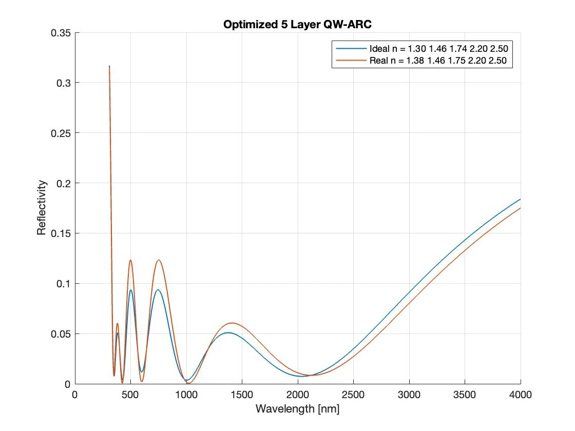
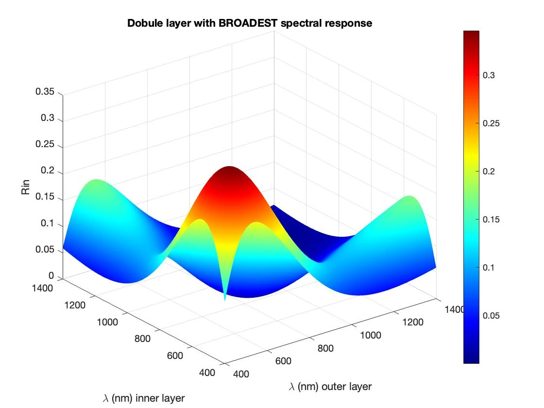
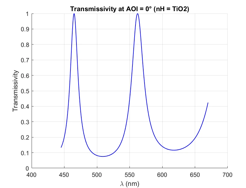
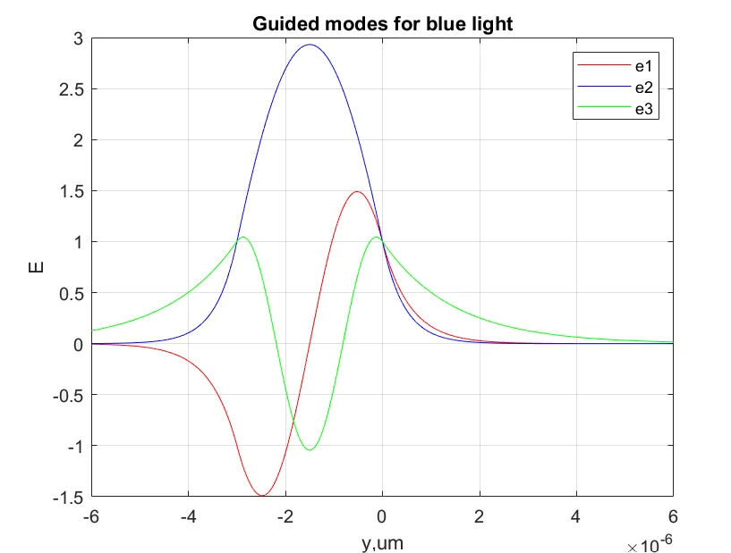
Four MATLAB projects for the Photonic Optical Components course: multilayer anti-reflection coatings for GaAs solar cells with AM1.5-weighted optimization, Fabry-Pérot filters and DBR mirrors using the transfer matrix method, an RGB waveguide combiner, and insertion losses in fiber junctions.

MATLAB · with Lorenzo Fiore · github.com/bobbisasha/poc_sf

Reflectivity of an optimized 5-layer quarter-wave ARC: ideal and real indices
Double-layer ARC reflectivity as a function of the design wavelengths
Transmissivity of the TiO2/MgF2 Fabry-Pérot filter at normal incidence
Guided modes for blue light in the RGB waveguide combiner
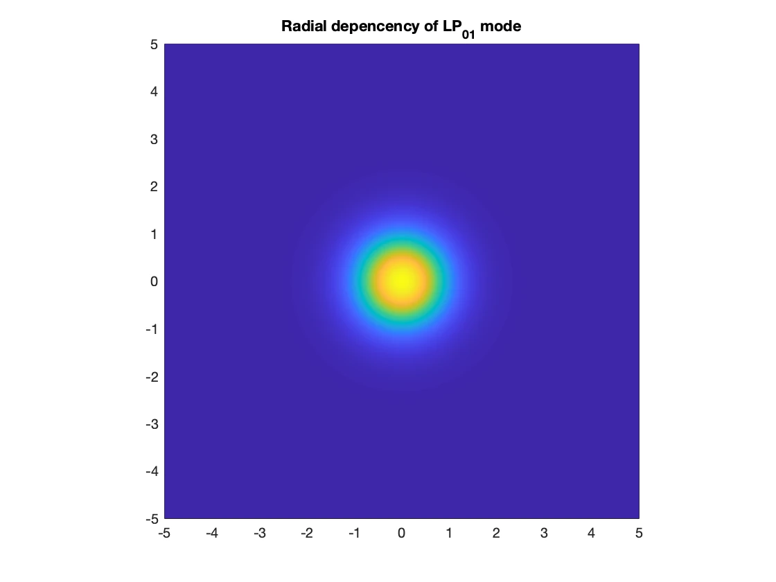
Radial distribution of the LP01 mode in a single-mode fiber

stm32 · embedded C · 2024

Bare-metal firmware on ARM Cortex-M4

Lab exercises on the Nucleo-F401RE developed in STM32CubeIDE, first with register-level LL drivers and then with the HAL: timers and output compare, EXTI interrupts, ADC sampling with USART output, and input-capture frequency measurement driving a PWM duty cycle.

C · STM32CubeIDE · github.com/bobbisasha/ST32_LABS

Board
Nucleo-F401RE
MCU
STM32F401RET6 · Cortex-M4 up to 84 MHz
Toolchain
STM32CubeIDE · arm-none-eabi-gcc · ST-LINK
Drivers
Register-level LL (labs 8–9) · HAL (lab 10)
Peripherals
TIM3 · TIM4 · EXTI · ADC1 · USART2
Serial
USART2 → ST-LINK Virtual COM · 115200 8-N-1
Nucleo-F401RE board
lab8_timers_interrupts_adc/ex1_2_tim3_timer/main.c excerpt
LL_TIM_WriteReg(TIM3, CR1, LL_TIM_ReadReg(TIM3, CR1) | 0x0001);
LL_TIM_WriteReg(TIM3, CCR2, 40);
LL_TIM_WriteReg(TIM3, CCR1, 200);

while (1)
{
  if ((LL_TIM_ReadReg(TIM3, SR) & 0x0002) == 0x0002) {
    LL_TIM_WriteReg(TIM3, SR, LL_TIM_ReadReg(TIM3, SR) ^ 0x0002);
    LL_GPIO_WriteReg(GPIOA, ODR, LL_GPIO_ReadReg(GPIOA, ODR) ^ 0x0400);
    LL_TIM_WriteReg(TIM3, CCR1, LL_TIM_ReadReg(TIM3, CCR1) + 200);
  }
  if ((LL_TIM_ReadReg(TIM3, SR) & 0x0004) == 0x0004) {
    LL_TIM_WriteReg(TIM3, SR, LL_TIM_ReadReg(TIM3, SR) ^ 0x0004);
    LL_GPIO_WriteReg(GPIOB, ODR, LL_GPIO_ReadReg(GPIOB, ODR) ^ 0x0400);
    LL_TIM_WriteReg(TIM3, CCR2, LL_TIM_ReadReg(TIM3, CCR2) + 40);
  }
}
lab8_timers_interrupts_adc/ex1_4_adc_usart/main.c excerpt
//ENABLE DELL ADC e SWSTART
LL_ADC_WriteReg(ADC1, CR2, LL_TIM_ReadReg(ADC1, CR2) | 0x1);
LL_ADC_WriteReg(ADC1, CR2, LL_TIM_ReadReg(ADC1, CR2) | (1 << 30));
//ENABLE TIM3
LL_TIM_WriteReg(TIM3, CR1, LL_TIM_ReadReg(TIM3, CR1) | 0x0001);

while (1)
{
  // Controlla il bit EOC (End Of Conversion)
  int eoc = LL_ADC_ReadReg(ADC1, SR) & 0x0010;
  if (eoc == 0x0010) {
    // Azzeramento del bit EOC
    LL_ADC_WriteReg(ADC1, SR, LL_ADC_ReadReg(ADC1, SR) | 0x0010);
    // Leggi il valore dal registro dati dell'ADC
    double ridden_value = LL_ADC_ReadReg(ADC1, DR);
    newRef = ((-0.04675*ridden_value)+ 14.374) * ridden_value;
  }
  if ((LL_TIM_ReadReg(TIM3, SR) & 0x0002) == 0x0002) {
    //toggle PB10
    LL_GPIO_WriteReg(GPIOB, ODR, LL_GPIO_ReadReg(GPIOB, ODR) ^ 0x0400);
    //Aggiorno soglia OUTPUT COMPARE
    LL_TIM_WriteReg(TIM3, CCR1, LL_TIM_ReadReg(TIM3, CCR1) + newRef);
    //Azzero il bit 1 dello state register
    LL_TIM_WriteReg(TIM3, SR, LL_TIM_ReadReg(TIM3, SR) & 0xFFFD);
  }
}
lab10_hal_timers_pwm/ex2_1_freq_measure_pwm/main.c excerpt
HAL_TIM_IC_Start_IT(&htim3, TIM_CHANNEL_1);
HAL_TIM_PWM_Start(&htim4, TIM_CHANNEL_1);

void HAL_TIM_IC_CaptureCallback(TIM_HandleTypeDef *htim) {
  static last = 0;
  int current;
  if (htim == &htim3) {
    current = htim->Instance->CCR1;
    if (last <= current) {
      period = current - last;
    }
    else {
      period = 65535 - last + current;
    }
    last = current;
    freq = 1/(period/(84*1e4));
    int newDC = 41 + ((freq / 280 )- 22.857);
    newDC = ceil(newDC);
    __HAL_TIM_SET_COMPARE(&htim4, TIM_CHANNEL_1, newDC);
  }
}

esd · VHDL on FPGA · 2024

Digital logic in VHDL on FPGA

VHDL coursework for the Electronic Systems Design course, targeting an Intel/Altera DE1 FPGA and developed in Quartus with ModelSim testbenches: a 64-bit ripple-carry adder, a 4×4 multiplier, counters, finite state machines and a datapath with control unit.

VHDL · Quartus · ModelSim · github.com/bobbisasha/ESD_LABS

Board
Intel/Altera DE1 (DE-series)
Toolchain
Quartus · ModelSim / GHDL
Clock
CLOCK_50 · 50 MHz
I/O
SW · KEY · HEX0–HEX5 · LEDR
Labs
arithmetic · counters and timers · FSMs · datapath + CU
Verification
*_tb / *_tbench testbenches
DE1 FPGA board
lab3_arithmetic_circuits/rca_64bit/rca_64bit.vhd excerpt
--CLOCK MANUALE
clk <= KEY(1);
resetn <=KEY(0);

--SALVA NEI REGISTRI D INGRESSO
regA : regn port map (signed(SW(127 downto 64)), clk, resetn, A_sign);
regB : regn port map (signed(SW(63 downto 0)), clk, resetn, B_sign);

A <= std_logic_vector(A_sign);
B <= std_logic_vector(B_sign);

-- Initialize Co(0)
Co(0) <= '0';

--SOMMATORE
sommatore : FOR i IN 0 TO 63 GENERATE
  full_adder_temp: full_adder PORT MAP (Co(i), A(i), B(i), S(i), Co(i+1));
END GENERATE sommatore;

--SALVA IN REGISTRO FINALE
regS : regn port map (signed(S),clk, resetn, uscita_sign);
uscita <= std_logic_vector(uscita_sign);

overflow <= Co(64) xor Co(63);

flip_flop0: flipflop PORT MAP (overflow, clk, resetn, v);
The hello_fsm state machine scrolls the word HELLO across the HEX5–HEX0 seven-segment displays hello_fsm · HEX5–HEX0 HEX5 HEX4 HEX3 HEX2 HEX1 HEX0 H E L_0 L O B B = blank display Each state emits a letter; a 6-stage shift register scrolls it across the displays.
lab5_finite_state_machines/hello_fsm/hello_fsm.vhd excerpt
TYPE state_type is (H, E, L,L_0, O, B);

reg0: regn port map (serial_in, clock_local, reset_local, reg_out(2 downto 0));

registri: for i in 1 to 5 generate
reg: regn port map(reg_out((3*i)-1 downto (3*i)-3), clock_local,
                   reset_local, reg_out((3*i)+2 downto 3*i));
end generate;

process(clock_local,reset_local)
Begin
  --reset asincrono
  if(reset_local = '0') then
  current_state <= H;

  elsif(Clock_local'EVENT AND Clock_local = '1') then

  case current_state is
    when H => current_state <= E;
    when E => current_state <= L_0;
    when L_0 => current_state <= L;
    when L => current_state <= O;
    when O => current_state <= B;
    when B => current_state <= H;
  END CASE;
  END IF;
End process;
lab5_finite_state_machines/hello_fsm/SevenSegmentDecoder.vhd revised
-- Codes emitted by hello_fsm: H=001, E=010, L=011, O=100, B=101
-- Active-low segments, in order a..g (0 to 6)
architecture Behavioral of SevenSegmentDecoder is
begin
  process (letter_in)
  begin
    case letter_in is
      when "001" =>  -- H
        segments_out <= "1001000";
      when "010" =>  -- E
        segments_out <= "0110000";
      when "011" =>  -- L
        segments_out <= "1110001";
      when "100" =>  -- O
        segments_out <= "0000001";
      when others => -- B: blank display
        segments_out <= "1111111";
    end case;
  end process;
end architecture Behavioral;
Lab 6 block diagram: memories, datapath, counters and FSM control unit Lab 6 · datapath + control unit MEM A 1024 × 8 Datapath REG 0–3 · shift ADD/SUB 17 bit AVG · HIGH · INB MEM B 1024 × 8 ext_data addr A · 10 bit alarm · 4 bit flag addr B · 10 bit Control unit · FSM enable · select · cs/rd/wr idle → load_A → init → shift 0–3 → average → diff_1 save_high → diff_2 → alrm_count → load_B → shift 0–3 | finish start rst done Irrigation monitor: samples in memory, averages and differences, alarm.
lab3_arithmetic_circuits/rca_64bit/rca_64bit_tbench.vhd excerpt
constant CLOCK_PERIOD : time := 5 ns;  -- Periodo del clock

BEGIN process
begin
  for i in 1 to 63 loop
    for j in 1 to 63 loop
      SW_TB(127 DOWNTO 64) <= std_logic_vector(to_signed(i, 64));
      SW_TB(63 DOWNTO 0) <= std_logic_vector(to_signed(j, 64));
      KEY_TB <= "11";
      wait for CLOCK_PERIOD;  -- Aspetta un fronte di clock per ogni coppia di valori
      KEY_TB <= "01";
      wait for CLOCK_PERIOD;
    end loop;
  end loop;
  wait;
end process;

DUT: rca_64bit port map(SW_TB, KEY_TB, LEDR_TB, HEX_TB);

Experience

  1. Apr 2026 — Sep 2026

    ART S.p.A. — Radar Signal Processing Intern (MSc Thesis)

    Perugia, Italy · MSc thesis internship

    • Embedded radar signal-processing pipeline for automotive object detection on a Texas Instruments mmWave radar SoC.
    • DBSCAN clustering of radar detections.
    • Event-triggered tracking algorithm in Python.
    • FMCW waveform (chirp) parameter design.
    • Power optimization of the embedded implementation.

    TI mmWave · FMCW · DBSCAN · Object tracking · Python · Low power

  2. Sep 2025 — Feb 2026

    DET, Politecnico di Torino — Electronics Lab Teaching Assistant

    Department of Electronics and Telecommunications · Collaboration contract

    • Support for didactic cleanroom activities: thin-film deposition (CVD, PVD) and photoresist deposition.
    • Assistance to BSc and MSc students in electronics lab sessions and in the use of bench instrumentation.

    Cleanroom · CVD · PVD · Photoresist · Bench instrumentation

  3. Jan 2025 — Jun 2025

    DET, Politecnico di Torino — EMC Teaching Assistant

    Department of Electronics and Telecommunications · Collaboration contract

    • Support for BSc students in Electromagnetic Compatibility (EMC) exercise sessions.
    • Laboratory assistance on AM/FM modulation and interference, and on 50 Hz power-grid EMC interference.

    EMC · AM/FM modulation · 50 Hz interference

Education

  1. Oct 2024 — Dec 2026 (expected)

    Politecnico di Torino — MSc in Electronic Engineering (LM-29)

    Specialization: Nano and Micro Electronics

    • Thesis: radar-based object detection for automotive applications, in collaboration with ART S.p.A.
    • Coursework in VLSI, FPGA and MEMS design; cleanroom activities.
  2. Oct 2021 — Jul 2024

    Politecnico di Torino — BSc in Electronic Engineering (L-8)

Languages and courses

  1. Level

    English — B2 (CEFR) · Italian — native

  2. 2019

    New York, USA — English language course

  3. 2018

    Bournemouth, United Kingdom — English language course

Download the full CV

Contact

Interested in semiconductor process engineering and digital IC and MEMS design roles.

[email protected]